1- Extrait de ce document en Français lors
de la présentation parue dans "La Nature avril 1878"
par A.G. Bell J’imaginai un expédient pour déterminer
la hauteur, et crus posséder la priorité de la découverte,
qui consistait à faire vibrer un diapason devant la bouche
durant les accommodations des organes vocaux prises silencieusement.
Il fut constaté que chaque position de
voyelle renforçait tel ou tel diapason ou plusieurs diapasons
spécialement. L’idée d’accroître la puissance
de transmission d’un fil télégraphique de cette
manière me vint à l’esprit, et ce fut ce but pratique
que j’eus en vue, en commençant mes recherches sur la
téléphonie électrique. Il se trouve généralement
que dans le progrès de la science la complication conduit à
la simplification, et qu’en faisant l’histoire d’une
découverte scientifique, il est souvent utile de commencer
par la fin. Lorsque je porte un regard rétrospectif sur mes
recherches, je reconnais la nécessité de désigner,
par des noms spéciaux, une variété de courants
électriques qui peuvent produire des sons. J’appellerai
votre attention sur plusieurs espèces distinctes de courants
d’électricité que l’on pourrait appeler téléphoniques
. Afin que les particularités de ces courants soient bien comprises,
je prierai M. Frost de projeter sur l’écran une illustration
graphique de ces différentes variétés. La méthode
graphique de représenter des courants électriques, et
que nous voyons ici, est la meilleure que l’on puisse imaginer
pour étudier exactement les effets produits par diverses formes
d’appareils téléphoniques. Elle m’a fait concevoir
cette sorte particulière de courant téléphonique
que j’appellerai ici courant ondulatoire, et qui rend possible
la production artificielle du langage articulé par des moyens
électriques. 1 C. G. Page, la Production de la musique galvanique.
Journal de Sillimann, 1857, XXXIII, p.396; Journal de Silli- man,
1858, xxxiii, p. 118; Bibl. univ. (nouvelle série, 1859, n,
p. 598). Le courant durait aussi longtemps que l’émission
d’uné note musicale et s’arrêtait immédiatement
après la cessation du son. Pendant plusieurs années,
mon attention se porta presque exclusivement sur les moyens d’obtenir
un instrument interrupteur extrêmement rapide de circuit voltaïque
et destiné à prendre la place du diapason transmetteur
employé dans les recherches de Helmholtz. C’est un fait
singulier que d’importantes découvertes sont souvent faites
presque simultanément par plusieurs personnes en différentes
parties du monde, et que l’idée de la télégraphie
multiple, telle qu’il l’a développée dans
les divers diagrammes montrés à la Société,
paraît s’être présentée isolément
tant en Amérique qu’en Europe à quatre inventeurs
différents. Les détails eux-mêmes des arrangements
en circuit ont une très-grande ressemblance avec ceux qu’ont
proposés M. Cromwell Varley, de Londres, M. Elisha Gray, de
Chicago, M. Paul Lacour, de Copenhague, et M. Thomas Edison, deRewark
dans l’État de New-Jersey. Quant à la question
de priorité d’invention, je ne me propose pas de la discuter.
HISTOIRE DU TÉLÉPHONE RACONTÉE
PAR SON INVENTEUR. (Suite et fin.) 2- Version Anglaise
du Document origine
Special General Meeting, held at 25, Great George Street,
Westminster, on Wednesday, the 31st October, 1877.[Page 1] EXTRACTS OF PROCEEDINGS OF THE SOCIETY OF TELEGRAPH ENGINEERS. Professor Abel, C.B., F.R.S., President, in the Chair. The President: Gentlemen, the Council of the Society of Telegraph Engineers felt that they were sure of doing what the members would consider right in summoning a special meeting for the two-fold purpose of giving a welcome to Professor Bell to this country and affording the Members an opportunity of hearing from him an account, which he has been so good as to promise to give us, of the nature, history, and development of, what may well be called, one of the most interesting discoveries of our age. Our time is very precious this evening. We all desire to hear everything Professor Bell can tell us on this subject, and many gentlemen will probably desire afterwards to ask questions or discuss the subject, for I see present a great number of eminent scientific men. I will not waste another moment, but at once call upon Professor Bell to commence his discourse on the Electric Telephone. RESEARCHES IN ELECTRIC TELEPHONY. By Professor Alexander Graham Bell. [Page 2] which I have been so long engaged. Many years ago my attention was directed to the mechanism of speech by my father, Alexander Melville Bell, of Edinburgh, who has made a life-long study of the subject. Many of those present may recollect the invention by my father of a means of representing, in a wonderfully accurate manner, the positions of the vocal organs in forming sounds. Together we carried on quite a number of experiments, seeking to discover the correct mechanism of English and foreign elements of speech, and I remember especially an investigation in which we were engaged concerning the musical relations of vowel sounds. When vowel sounds are whispered, each vowel seems to possess a particular pitch of its own, and by whispering certain vowels in succession a musical scale can be distinctly perceived. Our aim was to determine the natural pitch of each vowel; but unexpected difficulties made their appearance, for many of the vowels seemed to possess a double pitch”one due, probably, to the resonance of the air in the mouth, and the other to the resonance of the air contained in the cavity behind the tongue, comprehending the pharynx and larynx. I hit upon an expedient for determining the pitch which at that time I thought to be original with myself. It consisted in vibrating a tuning-fork in front of the mouth while the positions of the vocal organs for the various vowel sounds were silently taken. It was found that each vowel position caused the reinforcement of some particular fork or forks.I wrote an account of these researches to Mr. Alex. J. Ellis, of London, whom I have very great pleasure in seeing here to-night. In reply he informed me that the experiments related had already been performed by Helmholtz, and in a much more perfect manner than I had done. Indeed, he said that Helmholtz had not only analysed the vowel sounds into their constituent musical elements, but had actually performed the synthesis of them.He had succeeded in producing, artificially, certain of the vowel sounds by causing tuning-forks of different pitch to vibrate simultaneously by means of an electric current. Mr. Ellis was kind enough to grant me an interview for the purpose of explaining the apparatus employed by Helmholtz in producing these extraordinary [Page 3] effects, and I spent the greater part of a delightful day with him in investigating the subject. At that time, however, I was too slightly acquainted with the laws of electricity fully to understand the explanations given; but the interview had the effect of arousing my interest in the subjects of sound and electricity, and I did not rest until I had obtained possession of a copy of Helmholtz great work,[1] and had attempted, in a crude and imperfect manner it is true, to reproduce his results. While reflecting upon the possibilities of the production of sound by electrical means, it struck me that the principle of vibrating a tuning-fork by the intermittent attraction of an electro-magnet might be applied to the electrical production of music. I imagined to myself a series of tuning-forks of different pitches, arranged to vibrate automatically in the manner shown by Helmholtz, each fork interrupting at every vibration a voltaic current; and the thought occurred, Why should not the depression of a key like that of a piano direct the interrupted current from any one of these forks, through a telegraph wire, to a series of electro-magnets operating the strings of a piano or other musical instrument, in which case a person might play the tuning-fork piano in one place and the music be audible from the electromagnetic piano in a distant city ?� The more I reflected upon this arrangement the more feasible did it seem to me; indeed, I saw no reason why the depression of a number of keys at the tuning-fork end of the circuit should not be followed by the audible production of a full chord from the piano in the distant city, each tuning-fork affecting at the receiving end that string of the piano with which it was in unison. At this time the interest which I felt in electricity led me to study the various systems of telegraphy in use in this country and in America. I was much struck with the simplicity of the Morse alphabet, and with the fact that it could be read by sound. Instead of having the dots and dashes recorded upon paper, the operators were in the habit of observing the duration of the click of the instruments, and in this way were enabled to distinguish by ear the various signals. [Page 4 ] It struck me that in a similar manner the duration of a musical note might be made to represent the dot or dash of the telegraph code, so that a person might operate one of the keys of the tuning-fork piano referred to above, and the duration of the sound proceeding from the corresponding string of the distant piano be observed by an operator stationed there. It seemed to me that in this way a number of distinct telegraph messages might be sent simultaneously from the tuning-fork piano to the other end of the circuit, by operators each manipulating a different key of the instrument. These messages would be read by operators stationed at the distant piano, each receiving operator listening for signals of a certain definite pitch, and ignoring all others. In this way could be accomplished the simultaneous transmission of a number of telegraphic messages along a single wire, the number being limited only by the delicacy of the listeners ear. The idea of increasing the carrying power of a telegraph wire in this way took complete possession of my mind, and it was this practical end that I had in view when I commenced my .In the progress of science it is universally found that complexity leads to simplicity, and in narrating the history of scientific research it is often advisable to begin at the end.In glancing back over my own researches I find it necessary to designate, by distinct names, a variety of electrical currents by means of which sounds can be produced, and I shall direct your attention to several distinct species of what may be termed telephonic� currents of electricity. In order that the peculiarities of these currents may be clearly understood, I shall ask Mr. Frost to project upon the screen a graphical illustration of the different varieties.The graphical method of representing electrical currents here shown is the best means I have been able to devise of studying in an accurate manner the effects produced by various forms of telephonic apparatus, and it has led me to the conception of that [Page 5] peculiar species of telephonic current here designated as undulatory, which has rendered feasible the artificial production of articulate speech by electrical means. A horizontal line (g g´) is taken as the zero
of current, and impulses of positive electricity are represented above
the zero line, and negative impulses below it, or vice versâ.The
vertical thickness of any electrical impulse (b or d),
measured from the zero line, indicates the intensity of the electrical
current at the point observed, and the horizontal extension of the electric
line (b or d) indicates the duration of the impulse .
[Page
8] A glance at figs. 3, 4, and 5 will show the arrangement of such instruments upon a telegraphic circuit, designed to enable a number of telegraphic despatches to be transmitted simultaneously along the same wire. The transmitters and receivers that are numbered alike have the same pitch or rate of vibration. Thus the reed of T´ is in unison with the reeds T´ and R´ at all the stations upon the circuit, so that a telegraphic despatch sent by the manipulation of the key K´ at the station shown in fig. 3 will be received upon the receiving instruments K´ at all the other stations upon the circuit. Without going into details, I shall merely say that the great defects of this plan of multiple telegraphy were found to consist, firstly, in the fact that the receiving operators were required to possess a good musical ear in order to discriminate the signals; and secondly, that the signals could only pass in one direction along the line (so that two wires would be necessary in order to complete communication in both directions). The first objection was got over by employing the device which I term a vibratory circuit-breaker,� shown in the next diagram, whereby musical signals can be automatically recorded. Fig. 6 shows a receiving instrument R, with a vibratory circuit-breaker v attached. The light spring-lever v overlaps the free end of the steel reed A, and normally closes a local circuit, in which may be placed a Morse-sounder or other telegraphic apparatus. When the reed A is thrown into vibration by the passage of a musical signal, the spring arm v is thrown upwards, opening the local circuit at the point 5. When the spring-arm v is so arranged as to have normally a much slower rate of vibration than the reed A1, the local circuit is found to remain permanently open during the vibration of A, the spring-arm v coming into contact with the point 5 only upon the cessation of the receiver™s vibration. Thus the signals produced by the vibration of the reed A [Page 11] are reproduced upon an ordinary telegraphic instrument in the local circuit.Fig. 7 shows the application of to autographic telegraphy. T, T´, &c., represent the reeds of transmitting instruments of different pitch, R, R´, &c., the receivers at the distant station of corresponding pitch, and, r, r´, &c., the vibratory circuit-breakers attached to the receiving instruments, and connected with metallic bristles, 21, resting upon chemically prepared paper P. The message, or picture, to be copied, is written upon a metallic surface, F_0, with non-metallic ink, and placed upon a metallic cylinder 7, connected with the main battery B; and the chemically prepared paper P, upon which the message is to be received, is placed upon a metallic cylinder connected with the local battery B´ at the receiving station. When the cylinders at either end of the circuit are rotated in the direction of the arrows”but not necessarily at the same rate of speed”a fac simile of whatever is written or drawn upon the metallic surface F_0 appears upon the chemically prepared paper P. [Page 12] The method by means of which the musical signals may be sent simultaneously in both directions along the same circuit is shown in our next illustration, figures 8, 9, and 10. The arrangement is similar to that shown in figures 3, 4, and 5, excepting that the intermittent current from the transmitting instruments is passed through the primary wires of an induction coil, and the receiving instruments are placed in circuit with the secondary wire. In this way free earth communication is secured at either end of the circuit, and the musical signals produced by the manipulation of any key are received at all the stations upon the line. The great objection to this plan is the extreme complication of the parts and the necessity of employing local and main batteries at every station. It was also found by practical experiment that it was difficult, if not impossible, upon either of the plans here shown, to transmit simultaneously the number of musical tones that theory showed to be feasible. Mature consideration revealed the fact that this difficulty lay in the nature of the electrical current employed, and was finally obviated by the invention of the undulatory current.It is a strange fact that important inventions are often made almost simultaneously by different persons in different parts of the world, and the idea of multiple telegraphy as developed in the preceding diagrams seems to have occurred independently to no less than four other inventors in America and Europe. Even the details of the arrangements upon circuit”shown in figures 3, 4, 5, and 8, 9, 10”are extremely similar in the plans proposed by Mr. Cromwell Varley of London, Mr. Elisha Gray of Chicago, Mr. Paul La Cour of Copenhagen, and Mr. Thomas Edison of Newark, New Jersey. Into the question of priority of invention, of course, it is not my intention to go to-night. [Page 13] [Page 14] That the difficulty in the use of an intermittent current may be more clearly understood, I shall ask you to accompany me in my explanation of the effect produced when two musical signals of different pitch are simultaneously directed along the same circuit. Fig. 11 shows an arrangement whereby the reeds a a´ of two transmitting instruments are caused to interrupt the current from the same battery, B. We shall suppose the musical interval between the two reeds to be a major third, in which case their vibrations are in the ratio of 4 to 5, i.e., 4 vibrations of a are made in the same time as 5 vibrations of a1. A2 and B2 represent the intermittent currents produced, 4 impulses of B2 being made in the same time as 5 impulses of A2. The line A2 + B2 represents the resultant effect upon the main line when the reeds a and a1 are simultaneously caused to make and break the same circuit, and from the illustration you will perceive that the resultant current, whilst retaining a uniform intensity, is less interrupted when both reeds are in operation than when one alone is employed. By carrying your thoughts still further you will understand that when a large number of reeds of different pitch or of different rates of vibration are simultaneously making and breaking the same circuit the resultant effect upon the main line is practically equivalent to one continuous current. It will also be understood that the maximum number of musical signals that can be simultaneously directed along a single wire without conflict depends very much upon the ratio which the make� bears to the break;� the shorter the contact made, and the longer the break, the greater the number of signals that can be transmitted without confusion, and vice versâ. The apparatus by means of which this theoretical conclusion has been verified is here to-night, and consists of an ordinary parlour harmonium, the reeds of which are operated by wind in the usual manner. In front of each reed is arranged a metal screw, against which the reed strikes in the course of its vibration. By adjusting the screw the duration [Page 15] of the contact can be made long or short. The reeds are connected with one pole of a battery, and the screws against which they strike communicate with the line-wire, so that intermittent impulses from the battery are transmitted along the line-wire during the vibration of the reeds. We now proceed to the next illustration. Without entering into the details of the calculation you will see that with a pulsatory current the effect of transmitting musical signals simultaneously is nearly equivalent to a continuous current of minimum intensity”see A2 + B2, fig. 12; but when undulatory currents are employed the effect is different”see fig. 13. The current from the battery B is thrown into waves by the inductive action of iron or steel reeds M M´, vibrated in front of electro-magnets e e´, [Page 16] placed in circuit with the battery; A2 and B2 represent the undulations caused in the current by the vibration of the magnetised bodies, and it will be seen that there are four undulations of B2 in the same time as five undulations of A2. The resultant effect upon the main line is expressed by the curve A2 + B2, which is the algebraical sum of the sinusoidal curves A2 and B2. A similar effect is produced when reversed undulatory currents are employed as shown in fig. 14, where the current is produced by the vibration of permanent magnets M M´ in front of electro-magnets (e e´), united upon a circuit without a voltaic battery. It will be understood from figs. 13 and 14 that the effect of transmitting musical signals of different pitches simultaneously along a single wire is not to obliterate the vibratory character of the current as in the case of intermittent and pulsatory currents, but to change the shapes of the electrical undulations. In fact, the effect produced upon the current is precisely analogous to the effect produced in the air by the vibration of the inducing bodies M M´. Hence it should be possible to transmit as many musical tones simultaneously through a telegraph wire as through the air. The possibility of using undulatory currents for the purposes of multiple telegraphy enabled me to dispense entirely with the complicated arrangements of the circuit shown in figs. 3, 4, 5, and 8, 9, 10, and to employ a single battery for the whole circuit, retaining only the receiving instruments formerly shown. This arrangement is represented in figs. 15, 16, and 17. Upon vibrating the steel reed of a receiver R, R´, at any station by any mechanical means, the corresponding reeds at all the other stations are thrown into vibration, reproducing the signal. By attaching the steel reeds to the poles of a powerful permanent magnet, as shown in fig. 19, the signals can be produced without the aid of a battery. [Page 17] [Page 18] I have formerly stated that Helmholtz was enabled to produce vowel sounds artificially by combining musical tones of different pitches and intensities. His apparatus is shown in fig. 18. Tuning-forks of different pitch are placed between the poles of electro-magnets (a1, a2, &c.), and are kept in continuous vibration by the action of an intermittent current from the fork b. Resonators 1, 2, 3, &c. are arranged so as to reinforce the sounds, in a greater or less degree, according as the exterior orifices are enlarged or contracted.Thus it will be seen that upon Helmholtz™s plan the tuning-forks themselves produce tones of uniform intensity, the loudness being varied by an external reinforcement; but it struck me that the same results would be obtained, and in a much more perfect manner, by causing the tuning-forks themselves to vibrate with different degrees of amplitude. I therefore devised the apparatus shown in fig. 19, which was my first form of articulating telephone. In this figure a harp of steel rods is employed attached to the poles of a permanent magnet N.S. When any one of the rods is thrown into vibration an undulatory current is produced in the coils of the electro-magnet E, and the [Page 19] electro-magnet E´ attracts the rods of the harp H´ with a varying force, throwing into vibration that rod which is in unison with that vibrated at the other end of the circuit. Not only so, but the amplitude of vibration in the one will determine the amplitude of vibration in the other, for the intensity of the induced current is determined by the amplitude of the inducing vibration, and the amplitude of the vibration at the receiving end depends upon the intensity of the attractive impulses. When we sing into a piano, certain of the strings of the instrument are set in vibration sympathetically by the action of the voice with different degrees of amplitude, and a sound, which is an approximation to the vowel uttered, is produced from the piano. Theory shows, that, had the piano a very much larger number of strings to the octave, the vowel sounds would be perfectly reproduced. My idea of the action of the apparatus, shown in fig. 19, was this: Utter a sound in the neighbourhood of the harp H, and certain of the rods would be thrown into vibration with different amplitudes. At the other end of the circuit the corresponding rods of the harp H´ would vibrate with their proper relations of force, and the timbre of the sound would be reproduced. The expense of constructing such an apparatus as that shown in fig. 19 deterred me from making the attempt, and I sought to simplify the apparatus before venturing to have it made. [Page 20] I have before alluded to the invention by my father of a system of physiological symbols for representing the action of the vocal organs, and I had been invited by the Boston Board of Education to conduct a series of experiments with the system in the Boston school for the deaf and dumb. It is well known that deaf mutes are dumb merely because they are deaf, and that there is no defect in their vocal organs to incapacitate them from utterance. Hence it was thought that my father™s system of pictorial symbols, popularly known as visible speech, might prove a means whereby we could teach the deaf and dumb to use their vocal organs and to speak. The great success of these experiments urged upon me the advisability of devising methods of exhibiting the vibrations of sound optically, for use in teaching the deaf and dumb. For some time I carried on experiments with the manometric capsule of Koenig, and with the phonautograph of Léon Scott. The scientific apparatus in the Institute of Technology in Boston was freely placed at my disposal for these experiments, and it happened that at that time a student of the Institute of Technology, Mr. Maurey, had invented an improvement upon the phonautograph. He had succeeded in vibrating by the voice a stylus of wood about a foot in length which was attached to the membrane of the phonautograph, and in this way he had been enabled to obtain enlarged tracings upon a plane surface of smoked glass. With this apparatus I succeeded in producing very beautiful tracings of the vibrations of the air for vowel sounds. Some of these tracings are [Page 21] shown in fig. 20. I was much struck with this improved form of apparatus, and it occurred to me that there was a remarkable likeness between the manner in which this piece of wood was vibrated by the membrane of the phonautograph and the manner in which the ossiculæ of the human ear were moved by the tympanic membrane. I determined therefore to construct a phonautograph modelled still more closely upon the mechanism of the human ear, and for this purpose I sought the assistance of a distinguished aurist in Boston, Dr. Clarence J. Blake. He suggested the use of the human ear itself as a phonautograph, instead of making an artificial imitation of it. The idea was novel and struck me accordingly, and I requested my friend to prepare a specimen for me, which he did. The apparatus, as finally constructed, is shown in fig. 21. The stapes was removed and a stylus of hay about an inch in length was attached to the end of the incus. Upon moistening the membrana-tympani and the ossiculæ with a mixture of glycerine and water, the necessary mobility of the parts was obtained; and upon singing into the external artificial ear the stylus of hay was thrown [Page 22] into vibration, and tracings were obtained upon a plane surface of smoked glass passed rapidly underneath. While engaged in these experiments I was struck with the remarkable disproportion in weight between the membrane and the bones that were vibrated by it. It occurred to me that if a membrane as thin as tissue paper could control the vibration of bones that were, compared to it, of immense size and weight, why should not a larger and thicker membrane be able to vibrate a piece of iron in front of an electro-magnet, in which case the complication of steel rods shown in my first form of telephone, fig. 19, could be done away with, and a simple piece of iron attached to a membrane be placed at either end of the telegraphic circuit. Fig. 22 shows the form of apparatus that I was then employing for producing undulatory currents of electricity for the purposes of multiple telegraphy. A steel reed A was clamped firmly by one extremity to the uncovered leg h of an electro-magnet E, and the free end of the reed projected above the covered leg. When the reed A was vibrated in any mechanical way, the battery current was thrown into waves, and electrical undulations traversed the circuit B E W E´, throwing into vibration the corresponding reed A´ at the other end of the circuit. I immediately proceeded to put my new idea to the test of practical experiment, and for this purpose I attached the reed A (fig. 23) loosely by one extremity to the uncovered pole h of the magnet, and [Page 23] fastened the other extremity to the centre of a stretched membrane of goldbeaters™ skin n. I presumed that upon speaking in the neighbourhood of the membrane n it would be thrown into vibration and cause the steel reed A to move in a similar manner, occasioning undulations in the electrical current that would correspond to the changes in the density of the air during the production of the sound; and I further thought that the change of the intensity of the current at the receiving end would cause the magnet there to attract the reed A´ in such a manner that it should copy the motion of the reed A, in which case its movements would occasion a sound from the membrane n´ similar in timbre to that which had occasioned the original vibration. The results, however, were unsatisfactory and discouraging. My friend Mr. Thomas A. Watson, who assisted me in this first experiment, declared that he heard a faint sound proceed from the telephone at his end of the circuit, but I was unable to verify his assertion. After many experiments attended by the same only partially-successful results, I determined to reduce the size and weight of the spring as much as possible. For this purpose I glued a piece of clock spring, about the size and shape of my thumbnail, firmly to the centre of the diaphragm, and had a similar instrument at the other end (fig. 24); we were then enabled to obtain distinctly audible effects. I remember an experiment made with this telephone, which at the time gave me great satisfaction and delight. One of the telephones was placed in my lecture-room in the Boston University, and the other in the basement of the adjoining building. One of my students repaired to the distant telephone to observe the effects of articulate speech, while I uttered the sentence, Do you understand what I say?� into the telephone placed [Page 24] in the lecture-hall. To my delight an answer was returned through the instrument itself, articulate sounds proceeded from the steel spring attached to the membrane, and I heard the sentence, Yes, I understand you perfectly.� It is a mistake, however, to suppose that the articulation was by any means perfect, and expectancy no doubt had a great deal to do with my recognition of the sentence; still, the articulation was there, and I recognised the fact that the indistinctness was entirely due to the imperfection of the instrument. I will not trouble you by detailing the various stages through which the apparatus passed, but shall merely say that after a time I produced the form of instrument shown in fig. 25, which served very well as a receiving telephone. In this condition my invention was exhibited at the Centennial Exhibition in Philadelphia. The telephone shown in fig. 24 was used as a transmitting instrument, and that in fig. 25 as a receiver, so that vocal communication was only established in one direction. Another form of transmitting telephone exhibited in Philadelphia intended for use with the receiving telephone (fig. 25) is represented by fig. 26.A platinum wire attached to a stretched membrane completed a voltaic circuit by dipping into water. Upon speaking to the membrane, articulate sounds proceeded from the telephone in the distant room. The sounds produced by the telephone became louder when dilute sulphuric acid, or a saturated solution of salt, was substituted for the water. Audible effects were also produced by the vibration of plumbago in mercury, in a solution of bichromate of potash, in salt and water, in dilute sulphuric acid, and in pure water.The articulation produced from the instrument shown in fig. 25 was remarkably distinct, but its great defect consisted in the fact that it [Page 25] could not be used as a transmitting instrument, and thus two telephones were required at each station, one for transmitting and one for receiving spoken messages. It was determined to vary the construction of the telephone shown in fig. 24, and I sought by changing the size and tension of the membrane, the diameter and thickness of the steel spring, the size and power of the magnet, and the coils of insulated wire around their poles, to discover empirically the exact effect of each element of the combination, and thus to deduce a more perfect form of apparatus. It was found that a marked increase in the loudness of the sounds resulted from shortening the length of the coils of wire, and by enlarging the iron diaphragm which was glued to the membrane. In the latter case, also, the distinctness of the articulation was improved. Finally, the membrane of goldbeaters™ skin was discarded entirely, and a simple iron plate was used instead, and at once intelligible articulation was obtained. The new form of instrument is that shown in fig. 27, and, as had been long anticipated, it was proved that the only use of the battery was to magnetize the iron core of the magnet, for the effects were equally audible when the battery was omitted and a rod of magnetized steel substituted for the iron core of the magnet. [Page 26] It was my original intention, as shown in fig. 19, and it was always claimed by me, that the final form of telephone would be operated by permanent magnets in place of batteries, and numerous experiments had been carried on by Mr. Watson and myself privately for the purpose of producing this effect. At the time the instruments were first exhibited in public the results obtained with permanent magnets were not nearly so striking as when a voltaic battery was employed, wherefore we thought it best to exhibit only the latter form of instrument.The interest excited by the first published accounts of the operation of the telephone led many persons to investigate the subject, and I doubt not that numbers of experimenters have independently discovered that permanent magnets might be employed instead of voltaic batteries. Indeed one gentleman, Professor Dolbear, of Tufts College, not only claims to have discovered the magneto-electric telephone, but I understand charges me with having obtained the idea from him through the medium of a mutual friend. A still more powerful form of apparatus was constructed by using a powerful compound horse-shoe magnet in place of the straight rod which [Page 27] had been previously used (see fig. 28). Indeed the sounds produced by means of this instrument were of sufficient loudness to be faintly audible to a large audience, and in this condition the instrument was exhibited in the Essex Institute, in Salem, Massachusetts, on the 12th Feb. 1877, on which occasion a short speech shouted into a similar telephone in Boston, sixteen miles away, was heard by the audience in Salem. The tones of the speaker™s voice were distinctly audible to an audience of 600 people, but the articulation was only distinct at a distance of about 6 feet. On the same occasion, also, a report of the lecture was transmitted by word of mouth from Salem to Boston, and published in the papers the next morning. From the form of telephone shown in fig. 27 to the present form of the instrument (fig. 29) is but a step. It is in fact the arrangement of fig. 27 in a portable form, the magnet F H being placed inside the handle and a more convenient form of mouthpiece provided. The arrangement of these instruments upon a telegraphic circuit is shown in fig. 30. And here I wish to express my indebtedness to several scientific friends in America for their co-operation and assistance. I would [Page 28] specially mention Professor Peirce and Professor Blake, of Brown University, Dr. Channing, Mr. Clarke, and Mr. Jones. In Providence, Rhode Island, these gentlemen have been carrying on together experiments seeking to perfect the form of apparatus required, and I am happy to record the fact that they communicated to me each new discovery as it was made, and every new step in their investigations. It was, of course, almost inevitable that these gentlemen should retrace much of the ground that had been gone over by me, and so it has happened that many of their discoveries had been anticipated by my own researches; still, the very honourable way in which they from time to time placed before me the results of their discoveries entitles them to my warmest thanks and to my highest esteem. It was always my belief that a certain ratio would be found between the several parts of a telephone, and that the size of the instrument was immaterial; but Professor Peirce was the first to demonstrate the extreme smallness of the magnets which might be employed. And here, in order to show the parallel lines in which we were working, I may mention the fact that two or three days after I had constructed a telephone of the portable form (fig. 29), containing the magnet inside the handle, Dr. Channing was kind enough to send me a pair of telephones of a similar pattern, which had been invented by the Providence experimenters. The convenient form of mouthpiece shown in fig. 29, now adopted by me, was invented solely by my friend Professor Peirce. I must also express my obligations to my friend and associate, Mr. Thomas A. Watson, of Salem, Massachusetts, who has for two years past given me his personal assistance in carrying on my researches.In pursuing my investigations I have ever had one end in view, the practical improvement of electric telegraphy; but I have come across many facts which, while having no direct bearing upon the subject of telegraphy, may yet possess an interest for you.[24]For instance, I have found that a musical tone proceeds from a piece of plumbago or retort-carbon when an intermittent current of electricity is [Page 29] passed through it, and I have observed the most curious audible effects produced by the passage of reversed intermittent currents through the human body. A rheotome was placed in circuit with the primary wires of an induction coil, and the fine wires were connected with two strips of brass. One of these strips was held closely against the ear, and a loud sound proceeded from it whenever the other slip was touched with the other hand. The strips of brass were next held one in each hand. The induced currents occasioned a muscular tremor in the fingers. Upon placing my forefinger to my ear a loud crackling noise was audible, seemingly proceeding from the finger itself. A friend who was present placed my finger to his ear, but heard nothing. I requested him to hold the strips himself. He was then distinctly conscious of a noise (which I was unable to perceive) proceeding from his finger. In this case a portion of the induced currents passed through the head of the observer when he placed his ear against his own finger: and it is possible that the sound was occasioned by a vibration of the surfaces of the ear and finger in contact.When two persons receive a shock from a Ruhmkorff™s coil by clasping hands, each taking hold of one wire of the coil with the free hand, a sound proceeds from the clasped hands. The effect is not produced when the hands are moist. When either of the two touches the body of the other a loud sound comes from the parts in contact. When the arm of one is placed against the arm of the other, the noise produced can be heard at a distance of several feet. In all these cases a slight shock is experienced so long as the contact is preserved. The introduction of a piece of paper between the parts in contact does not materially interfere with the production of the sounds, but the unpleasant effects of the shock are avoided.When an intermittent current from a Ruhmkorff™s coil is passed through the arms a musical note can be perceived when the ear is closely applied to the arm of the person experimented upon. The sound seems to proceed from the muscles of the fore-arm and from the biceps muscle. Mr. Elisha Gray[25] has also produced audible effects by the passage of electricity through the human body. [Page 30] An extremely loud musical note is occasioned by the spark of a Ruhmkorff™s coil when the primary circuit is made and broken with sufficient rapidity; when two rheotomes of different pitch are caused simultaneously to open and close the primary circuit a double tone proceeds from the spark.A curious discovery, which may be of interest to you, has been made by Professor Blake. He constructed a telephone in which a rod of soft iron, about six feet in length, was used instead of a permanent magnet. A friend sang a continuous musical tone into the mouthpiece of a telephone, like that shown in fig. 29, which was connected with the soft iron instrument alluded to above. It was found that the loudness of the sound produced in this telephone varied with the direction in which the iron rod was held, and that the maximum effect was produced when the rod was in the position of the dipping-needle. This curious discovery of Professor Blake has been verified by myself.When a telephone is placed in circuit with a telegraph line, the telephone is found seemingly to emit sounds on its own account. The most extraordinary noises are often produced, the causes of which are at present very obscure. One class of sounds is produced by the inductive influence of neighbouring wires and by leakage from them, the signals of the Morse alphabet passing over neighbouring wires being audible in the telephone, and another class can be traced to earth currents upon the wire, a curious modification of this sound revealing the presence of defective joints in the wire.Professor Blake informs me that he has been able to use the railroad track for conversational purposes in place of a telegraph wire, and he further states that when only one telephone was connected with the track the sounds of Morse operating were distinctly audible in the telephone, although the nearest telegraph-wires were at least forty feet distant.Professor Peirce has observed the most curious sounds produced from a telephone in connection with a telegraph wire during the aurora borealis; and I have just heard of a curious phenomenon lately observed by Dr. Channing. In the city of Providence, Rhode Island, there is an [Page 31] overhouse wire about one mile in extent with a telephone at either end. On one occasion the sound of music and singing was faintly audible in one of the telephones. It seemed as if some one were practising vocal music with a pianoforte accompaniment. The natural supposition was that experiments were being made with the telephone at the other end of the circuit, but upon inquiry this proved not to have been the case. Attention having thus been directed to the phenomenon, a watch was kept upon the instruments, and upon a subsequent occasion the same fact was observed at both ends of the line by Dr. Channing and his friends. It was proved that the sounds continued for about two hours, and usually commenced about the same time. A searching examination of the line disclosed nothing abnormal in its condition, and I am unable to give you any explanation of this curious phenomenon. Dr. Channing has, however, addressed a letter upon the subject to the editor of one of the Providence papers, giving the names of such songs as were recognised, with full details of the observations, in the hope that publicity may lead to the discovery of the performer, and thus afford a solution of the mystery.My friend Mr. Frederick A. Gower communicated to me a curious observation made by him regarding the slight earth connection required to establish a circuit for the telephone, and together we carried on a series of experiments with rather startling results. We took a couple of telephones and an insulated wire about 100 yards in length into a garden, and were enabled to carry on conversation with the greatest ease when we held in our hands what should have been the earth wire, so that the connection with the ground was formed at either end through our bodies, our feet being clothed with cotton socks and leather boots. The day was fine, and the grass upon which we stood was seemingly perfectly dry. Upon standing upon a gravel walk the vocal sounds, though much diminished, were still perfectly intelligible, and the same result occurred when standing upon a brick wall one foot in height, but no sound was audible when one of us stood upon a block of freestone.One experiment which we made is so very interesting that I must speak of it in detail. Mr. Gower made earth connection at his end of the line by standing upon a grass plot, whilst at the other end of the line I [Page 32] stood upon a wooden board. I requested Mr. Gower to sing a continuous musical note, and to my surprise the sound was very distinctly audible from the telephone in my hand. Upon examining my feet I discovered that a single blade of grass was bent over the edge of the board, and that my foot touched it. The removal of this blade of grass was followed by the cessation of the sound from the telephone, and I found that the moment I touched with the toe of my boot a blade of grass or the petal of a daisy the sound was again audible.The question will naturally arise, Through what length of wire can the telephone be used? In reply to this I may say that the maximum amount of resistance through which the undulatory current will pass, and yet retain sufficient force to produce an audible sound at the distant end, has yet to be determined; no difficulty has, however, been experienced in laboratory experiments in conversing through a resistance of 60,000 ohms, which has been the maximum at my disposal. On one occasion, not having a rheostat at hand, I may mention having passed the current through the bodies of sixteen persons, who stood hand in hand. The longest length of real telegraph line through which I have attempted to converse has been about 250 miles. On this occasion no difficulty was experienced so long as parallel lines were not in operation. Sunday was chosen as the day on which it was probable other circuits would be at rest. Conversation was carried on between myself, in New York, and Mr. Thomas A. Watson, in Boston, until the opening of business upon the other wires. When this happened the vocal sounds were very much diminished, but still audible. It seemed, indeed, like talking through a storm. Conversation though possible could be carried on with difficulty, owing to the distracting nature of the interfering currents.I am informed by my friend Mr. Preece that conversation has been successfully carried on through a submarine cable, sixty miles in length, extending from Dartmouth to the Island of Guernsey, by means of hand telephones similar to that shown in fig. 30. Footnotes:
[1]
Helmholtz. Die Lehre von dem Tonempfindungen. (English Translation
by Alexander J. Ellis, Theory of Tone.)
[2]
C. G. Page. The Production of Galvanic Music.� Silliman™s
Journ. 1837, xxxii. p. 396; Silliman™s Journ. July, 1837, p. 354;
Silliman™s Journ. 1838, xxxiii. p. 118; Bibl. Univ. (new series),
1839, ii. p. 398.
[3]
J. P. Marrian. Phil. Mag. xxv. p. 382; Inst. 1845, p. 20; Arch.
de l™Ã‰lectr. v. p. 195.
[4]
W. Beatson. Arch. de l™Ã‰lectr. v. p. 197; Arch. de Sc. Phys.
et Nat. (2d series), ii. p. 113.
[5]
Gassiot. See Treatise on Electricity,� by De la Rive,
i. p. 300.
[6]
De la Rive. Treatise on Electricity, i. p. 300; Phil. Mag.
xxxv. p. 422; Arch. de l™Ã‰lectr. v. p. 200; Inst. 1846, p. 83;
Comptes Rendus, xx. p. 1287; Comp. Rend. xxii. p. 432; Pogg. Ann.
lxxvi. p. 637; Ann. de Chim. et de Phys. xxvi. p. 158.
[7]
Matteucci. Inst. 1845, p. 315; Arch, de l™Ã‰lectr. v. 389.
[8]
Guillemin. Comp. Rend. xxii. p. 264; Inst. 1846, p. 30; Arch.
d. Sc. Phys. (2d series), i. p. 191.
[9]
G. Wertheim. Comp. Rend. xxii. pp. 336, 544; Inst. 1846, pp.
65, 100; Pogg. Ann. lxviii. p. 140; Comp. Rend. xxvi. p. 505; Inst.
1848, p. 142; Ann. de Chim. et de Phys., xxiii. p. 302; Arch. d. Sc.
Phys. et Nat. viii. p. 206; Pogg. Ann. lxxvii. p. 43; Berl. Ber. iv.
p. 121.
[10]
Elie Wartmann. Comp. Rend. xxii. p. 544; Phil. Mag. (3d series),
xxviii. p. 544; Arch. d. Sc. Phys. et Nat. (2d series), i. p. 419;
Inst. 1846, p. 290; Monatscher. d. Berl. Akad. 1846, p. 111.
[11]
Janniar. Comp. Rend, xxiii. p. 319; Inst. 1846, p. 269; Arch.
d. Sc. Phys. et Nat. (2d. series), ii. p. 394.
[12]
J. P. Joule. Phil. Mag. xxv. pp. 76, 225; Berl. Ber. iii. p.
489.
[13]
Laborde. Comp. Rend. l. p. 692; Cosmos, xvii. p. 514.
[14]
Legat. Brix. Z. S. ix. p. 125.
[15]
Reis. Téléphonie.� Polytechnic Journ. clxviii. p. 185;
Böttger™s Notizbl. 1863, No. 6.
[16]
J. C. Poggendorff. Pogg. Ann. xcviii. p. 192; Berliner Monatsber.
1856, p. 133; Cosmos, ix. p. 49; Berl. Ber. xii. p. 241; Pogg. Ann.
lxxxvii. p. 139.
[17]
Du Moncel. Exposé, ii. p. 125; also, iii. p. 83.
[18]
Delezenne. Sound produced by Magnetization,� Bibl. Univ.
(new series), 1841, xvi. p. 406.
[19]
See London Journ. xxxii. p. 402; Polytechnic Journ. ex. p. 16; Cosmos,
iv. p. 43; Glösener”Traité général, &c. p. 350; Dove.-Repert.
vi. p. 58; Pogg. Ann. xliii. p. 411; Berl. Ber. i. p. 144; Arch. d.
Sc. Phys. et Nat. xvi. p. 406; Kuhn™s Encyclopædia der Physik,
pp. 1014-1021.
[20]
Gore. Proceedings of Royal Society, xii. p. 217.
[21]
C. G. Page. Vibration of Trevelyan™s bars by the galvanic
current.� Silliman™s Journal, 1850, ix. pp. 105-108.
[22]
Sullivan. Currents of Electricity produced by the vibration
of Metals,� Phil. Mag. 1845, p. 261; Arch. de l™Ã‰lectr. x. p.
480.
[23]
The full description of this figure will be found in Mr. Alexander
J. Ellis™s translation of Helmholtz™s work, Theory of Tone.�
[24]
See Researches in Telephony.”Trans. of American Acad. of
Arts and Sciences, vol. xii. p. 1.
[25]
Elisha Gray. Eng. Pat. Spec. No. 2646, Aug. 1874.
|
|||||||||||||||||||||||||||||||||||||||||||||||||||
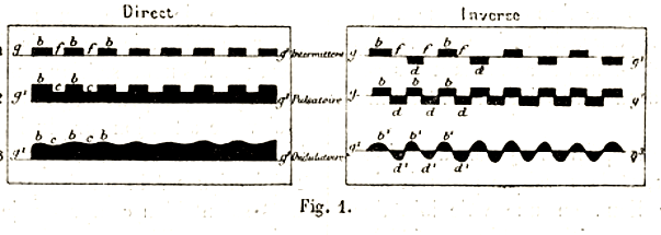
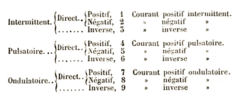
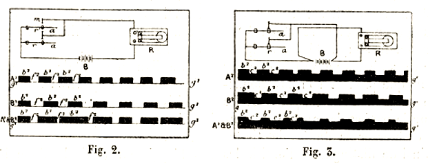
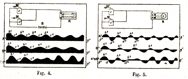
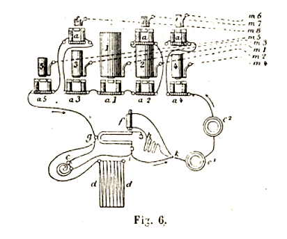
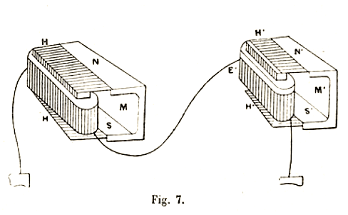
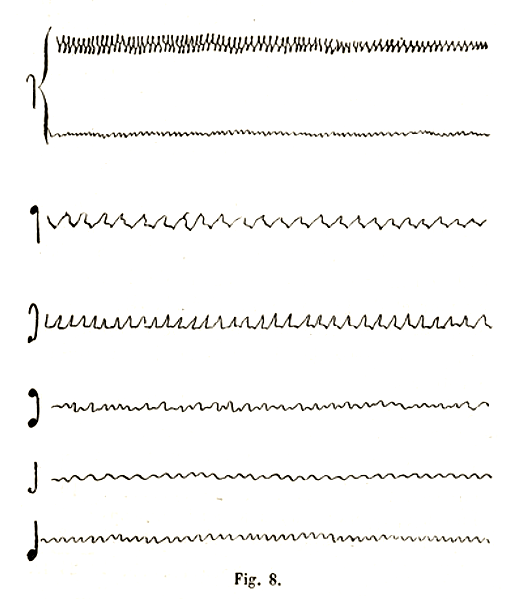
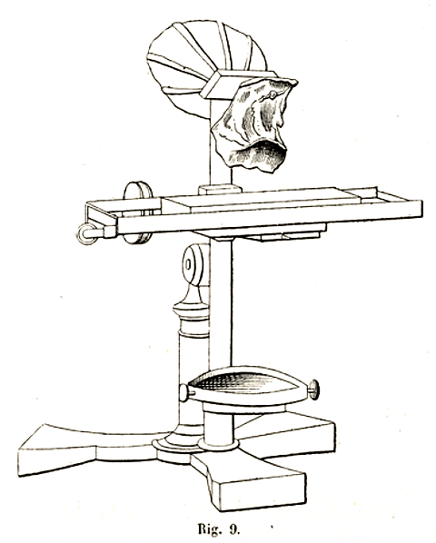
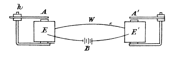 Fig. 1
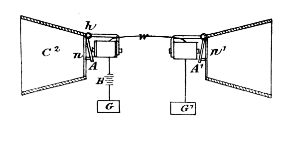 Fig.
2
Fig.
2 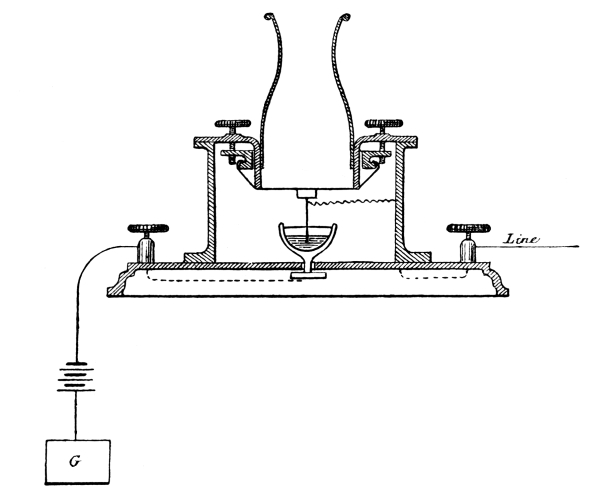 Fig. 3
 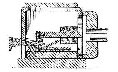 Fig.4
Fig.4 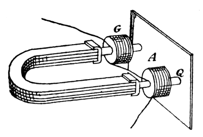 Fig. 5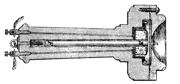
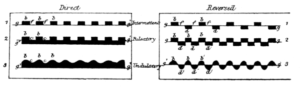 Fig. 1.


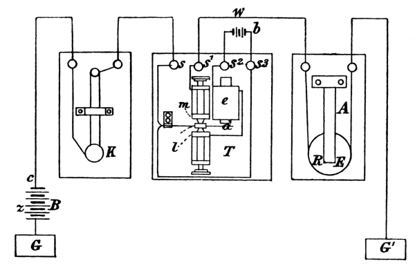 Fig. 2.
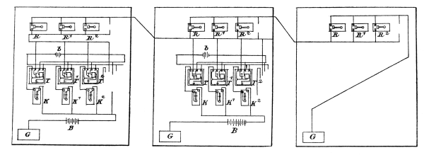 Fig. 3.
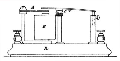 Fig.
6.
Fig.
6.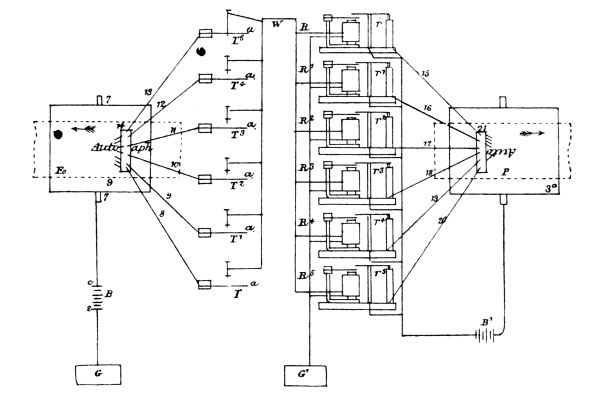 Fig.
7.
Fig.
7.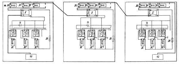 Fig. 8.
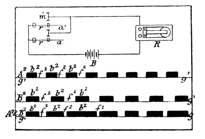 Fig. 11.
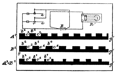 Fig. 12.
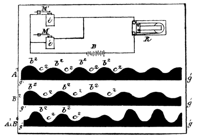 Fig. 13.
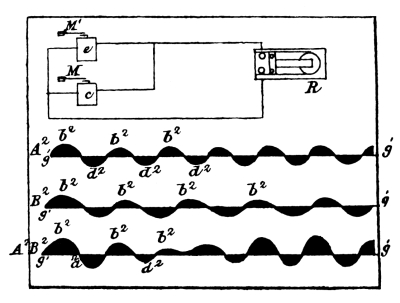 Fig. 14.
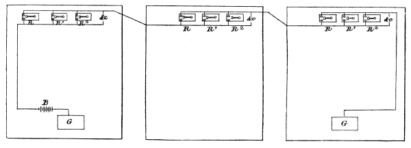 Fig. 15.
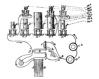 Fig. 18.
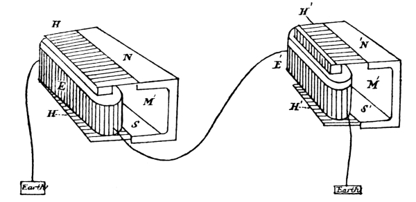 Fig. 19.
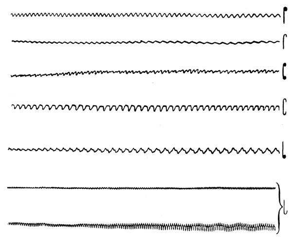 Fig. 20.
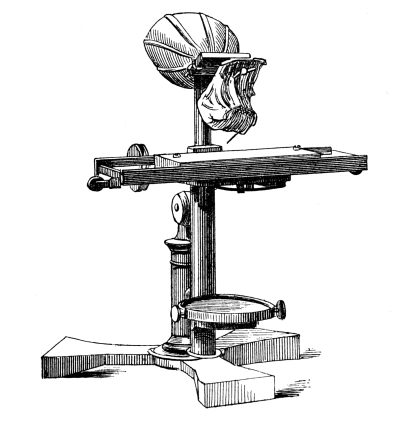 Fig. 21.
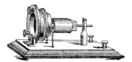 Fig. 24.
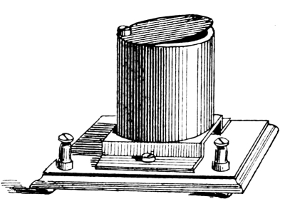 Fig. 25.
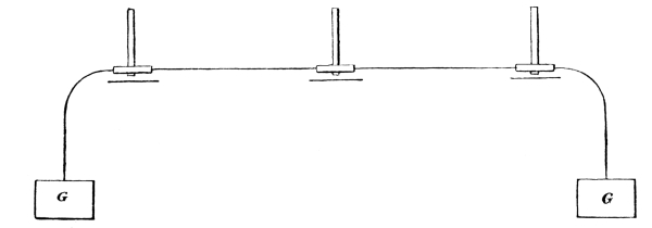 Fig. 30.